")
**NOTE: A Manufacturer’s recall has been issued for this device. In rare cases, when the TEST button is pressed, the detector will show ALARM and stop functioning. It is highly recommended that these devices not be used for CO gas detection.**
MCT-442 SMA wireless Carbon Monoxide (CO) detector gives early warning of CO poisoning danger, preventing damage to vital organs and even death. As a fully supervised wireless detector, the MCT-442 SMA enables a rapid and effective response to remove the CO poisoning danger, protecting children, the elderly and even pets, from an invisible and potentially deadly threat. High accuracy and reliability MCT-442 SMA CO detector utilizes a sophisticated electrochemical sensor to provide linear output in proportion to CO gas concentration, which is the most accurate technology available for CO detection. The sensor’s flexible and miniature construction results in high resistance to shocks and vibrations. A sophisticated microprocessor receives data from a sensor, calculates the CO level and leak duration, and provides an alarm before dangerous CO levels are present. The detector has a five-year life and an expiration timer that notifies users when the detector should be replaced. As a battery-operated device, detection continues non-stop, even during power outages.
Specifications Installation Pairing Resetting
Features and Specifications
- Fully wireless and supervised detector transmits alarm and functionality alerts to thePowerMax® control panel, which notifies the user and/or the central station
- Gives early warning of carbon monoxide (CO) poisoning danger, providing visual and audible alarm indications when CO is detected
- Loud built-in alarm buzzer (95db) and a large flashing LED alarm
- Continuous auto-testing and manual testing
- Five-year life, with end-of-life notification
- Battery operated, ensuring continuous protection; low battery and sensor end of life indications
- Easy wall or ceiling installation (with bracket), with no need for cabling work; simple battery replacement
- Back tamper
Tech Specs
- Battery Type: 9V battery (lithium or alkaline)
- Battery Life: 1.6 years
- Dimension: 5 x 1.56 in
- Operating Temperature: Exterior: 32°F to 1
Installation
Mounting and Installing
The sensor can be mounted on a wall or ceiling. For EN approved sites, only ceiling installation is allowed. It must be mounted with its bracket (when it is attached to its bracket the tamper switch is pressed and the sensor automatic reset is performed).
1) Locate the bracket on mounting surface so that the word “UP” is located as shown (so that the sensors stickers text will be easily readable).
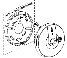
2) Mark and drill 2 holes in mounting surface. Fasten the bracket to the mounting surface with 2 screws.
3) Align sensors tabs with the bracket slots and rotate the sensor as shown. Pull the sensor to verify that is is securely attached.
Warnings
• Installation must be performed by a qualified individual. Failure to properly install, test and maintain a CO sensor may cause it to fail, resulting in loss of life!
• Installation of the CO sensor should not be used as a substitute for proper installation, use and maintenance of fuel burning appliances, including appropriate ventilation and exhaust systems.
• Unauthorized removal of the unit from the bracket will initiate a tamper alert!
TESTING
Press the test button until the built-in buzzer sounds 1 beep and the red, green and yellow LEDs flash sequentially. This means that the local test is successful.
WARNING
The test switch is the only proper way to test the CO sensor. Never use vehicle exhaust! Exhaust may cause permanent damage and void your warranty.
Choosing a Location to Install
Selecting a suitable location is critical for the CO sensor. The Consumer Product Safety Commission (CPSC) recommends to use at least one CO sensor per household, located near as possible to sleeping area of the home, because the human body is most vulnerable to the CO gas effect during sleeping hours. For added protection, install additional CO sensor in every separate bedroom and on every level of your home. If your bedroom hallway is longer than 14 meters (40 feet), install a CO sensor at BOTH ends of the hallway. Install an additional sensor 6 meters (20 feet) away from the furnace or fuel burning heat source.
Where NOT to Install
1. In location where temperature may be below -10°C (14°F) or above 40°C (104°F).
2. In locations where humidity is below 10% or above 93% RH.
3. Near paint thinner fumes.
4. Near air conditioners, furnaces, stoves, fireplaces and any other ventilation source that may interfere with the CO gas entering the sensor.
5. In locations where furniture or draperies may obstruct the air flow.
6. In exhaust streams from gas engines, vents, flues or chimneys.
7. Where dirt or dust could collect and block the sensor and stop its working.
8. In locations that can be reached by children.
9. In turbulent air from ceiling fans.
10. In close proximity to an automobile exhaust pipe – this will damage the sensor.
Pairing
Sensors can be added to your system during activation, or at a later time. If you want to add a sensor that was not included with the original Touchstone package, make sure your service provider supports it.
Note: If you are attempting to pair a sensor that has been previously deleted from the Hub, it will be necessary to default the sensor.
To add a sensor, click SETTINGS on the toolbar to display the Settings page. The number in the upper right hand corner of each icon indicates how many instances of that type of device have been installed already.
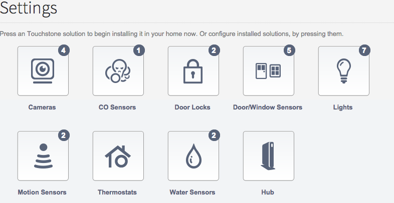
Click the type of sensor you want to add(i.e. door/winow, motion, etc) to display the sensor’s settings.
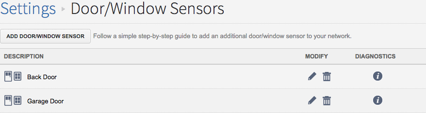
Click Add Door/Window Sensor(or whichever type of sensor you are attempting to add) and follow the on screen prompts.
Resetting
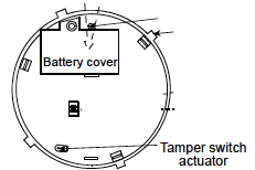
- Hold down the tamper switch on the bottom of the device.
- Insert the battery into the sensor. Wait for the RF module’s green LED to light. In order to see the green LED on the circuit board, the cover must be separated from the housing (to expose the circuit board) .
- Release the tamper switch and press it again within 4 seconds. When the sensor is in pairing mode, the green LED starts to blink and you are ready to pair the device to your Touchstone system.
Deleting
When you delete a sensor, Touchstone disables any rules that reference the sensor.
To delete a sensor, click SETTINGS on the toolbar to display the settings page.
Click the type of sensor that you would like to delete to display the sensor’s settings page.
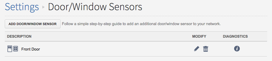
Click the ![]() icon next to the sensor that you would like to edit and you will see the option to rename the sensor. Rename it and click save.
icon next to the sensor that you would like to edit and you will see the option to rename the sensor. Rename it and click save.
OR
Click the ![]() icon next to the sensor that you would like to delete and you will see a confirmation dialog displayed.
icon next to the sensor that you would like to delete and you will see a confirmation dialog displayed.
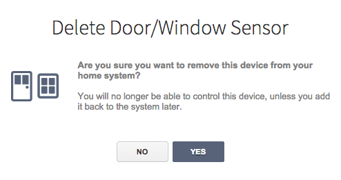
Click YES to remove the sensor from your system.