")
Salus Optima is a dual power smart ZigBee HA compliance thermostat. Without any common wire, it can be powered by two AA alkaline batteries only. The battery life is about two years under normal operation with high power ZigBee communication.Salus Optima is a dual power smart ZigBee HA compliance thermostat. Without any common wire, it can be powered by two AA alkaline batteries only. The battery life is about two years under normal operation with high power ZigBee communication.
Specifications Installation Configuration Pairing
Features and Specifications
- ZigBee HA1.2 compliance with power amplification for excellent RF range.
- Two-year battery life with only two AA batteries.
- Supporting both AC and battery power.
- Simple but elegant outlook with touch ring set point and control.
- Support 3 heat / 2 cool heat pump and 2 heat / 2 cool convention systems.
- Both the ZigBee and thermostat microprocessor are upgradable through OTA
- Built-in humidity sensor
Technical Specs
- Battery Type: 2 x AA batteries, 3V
- Battery Life: 2 years
- Dimension: 4.21 x 4.21 x 1.12
- Operating Temperature: 32°F to 104°F
Installation
Before you begin installing your thermostat, please be advised that It is always a good practice to consult the owner’s manual for your HVAC system. If necessary, consult an HVAC technician to ensure proper installation.
Turn off the heating and/or cooling
Turn OFF the breakers or remove the fuses to the heating and/or cooling systems at the electrical panel.
In some regions, there may be a switch located near the furnace.
Determining Wiring Configuration

- Remove the old thermostat to expose the wiring terminals.
- Take a picture of the wiring for future reference.
- Note the terminals attached to each wire and attach the matching label to the ends of the wires. Use the following table as a reference.
A jumper connects RC and RH as most combination heat and cooling systems use a single transformer. For systems where separate transformers are used, remove the jumper in place across the RC and RH terminals.
| Optima Thermostat Wiring Reference | |||
|---|---|---|---|
| Gas, Electric, or Oil (non-HP) | Heat Pump (HP) | ||
| R or RC* | 24 VAC for Cooling system | R or RC* | 24 VAC for Cooling system |
| RH* | 24 VAC for Heating system | RH* | 24 VAC for Heating system |
| C | 24 VAC common return | C | 24 VAC common return |
| — | Reserved | L | System monitor |
| Y or Y1 | Single / 1st stage cooling | Y or Y1 | Single / 1st stage compressor |
| Y2 | 2nd stage cooling | Y2 | 2nd stage compressor |
| W or W1 | Single / 1st stage heating | W or W1 | Emergency heat |
| W2 | 2nd stage heating | O/B | Changeover Valve |
| G | Fan Signal | G | Fan Signal |
| — | Reserved | — | Reserved |
Remove old thermostat terminals
Remove the old thermostat wiring terminals from the wall, taking care not to allow the wiring to fall inside the wall.
Tip: Wrap the wire ends around a long stick such as a pencil to prevent the wires from falling into the wall.
Install Mounting Plate

Remove the Mounting Plate from the back of the Optima thermostat. Use the included wall anchors and screws to attach the Mounting Plate to the wall, making sure the wires run through the center opening. Use the Trim Plate vertically or horizontally if desired.
Attach Wiring

Before attaching the wires, match the wire (using the labels) to its corresponding terminal. Refer to the picture of the wiring taken earlier if necessary.
• Open the terminal by lifting the latch up.
• Push each wire into the hole of the terminal and push the latch down to secure the wire.
Install Batteries

Insert the alkaline batteries into the back of the thermostat. Make sure the polarity of the batteries is correct. After inserting the batteries, the display will flash all the segments, followed by the version number of the firmware, then display US / CA with a blinking US.
Initial Configuration

When configuring the thermostat, press the + or – button or use the slider ring to cause the desired value to blink, then press MODE to select the value. Using the table at right, select the country, then the type of system. After this configuration, the thermostat will display the Home Screen, and be ready for attachment to the Mounting Plate.
Attach Thermostat To Mounting Plate

Attach the thermostat to the Mounting Plate by aligning the connector pins and the plastic retention posts and pushing the thermostat onto the Mounting Plate. Make sure the connector pins are not bent and that the thermostat is fully seated on the Mounting Plate.
Turn Power Back On To The HVAC System
Go to the electrical service panel or furnace switch and turn the HVAC system back on.
Configure Thermostat
The thermostat can now be used as a basic local thermostat. To enable the enhanced features, additional settings need to be configured. See the Configuring the Thermostat section by clicking the ‘Configuring’ link below.
Preparing the Thermostat to PAIR
- Go to the PAIR menu item on the OPTIMA thermostat (Hold Mode down for 3 seconds until CLOCK is displayed. Use the +/- to scroll until PAIR is displayed).
- Press MODE to select pairing mode. Display will show WILL PAIR.
- Press MODE again to enter pairing mode. Display will show the number 10 and Pairing.
- Wait for the connected home system to recognize the thermostat. The thermostat will blink IDENTIFY and return to the Home Screen when the thermostat has been added to the system. The blinking IDENTIFY will go away after 3 minutes.
Once you have completed the installation process, return to the activation flow to add your device to your system.
Configuration
Configuration Mode is for experienced or authorized installers
CONFIGURING THE THERMOSTAT
To enter Configuration Mode, press MODE for 3 seconds. The display will clear and show a blinking CLOCK in the Label Area. In Configuration Mode, after 20 seconds of inactivity, the thermostat will exit Configuration Mode and return to the Home Screen.
Configuration Menus
Following are the functions that can be configured on the OPTIMA thermostat. When a sub-menu option is selected, the thermostat will return to the sub-menu title to indicate that the option has been stored. The + or – buttons can be used to select another menu item at the same level. To return to a higher-level menu item at any time, press the FAN/HOLD button.
CLOCK
- Time Zone – default is PST

12/24 hour format
- 12 hr – Use AM/PM indicators (default)
- 24 hr – Use 24 hour notation
Time
- Set current time in hours and minutes (defaults to midnight)
Date
- Set month, day, and year (defaults to Jan 1, 2014)
Daylight Savings Time
- ON – Daylight Savings Time is observed (default)
- OFF – Daylight Savings Time is NOT observed
SETTINGS
Country – sets operating limits and defaults for time zone and temperature units
- US – United States values
- CA – Canadian values
HVAC Type
- HP – Heat Pump
- O – O reverse valve (default)
- B – B reverse valve
- NON-HP – Electric, Gas, or Oil heat
- FAN HG – Fan functionality for gas heating (default)
- FAN HE – Fan functionality for electric or oil heating
Temperature Units
- ºF – Use Fahrenheit units for temperature (US default)
- ºC – Use Celsius/Centigrade units for temperature (CA default)
Offset
Should the temperature sensor need calibration. This value is added to the sensed temperature to determine the room temperature.
Range:
- ±7ºF in 1 degree increments
- ±4ºC in 0.5 degree increments
- Default: 0 degrees
Span
Temperature variance before taking action. This value determines the amount of temperature variation allowed before calling for heat or cooling. Example: a span of 1ºF with a set point of 70ºF will allow the room temperature to swing between 69ºF and 71ºF without taking action.
- Range: 0.5 – 2.0ºF in 0.5 degree increments
- 0.25 – 1.0ºC in 0.25 degree increments
- Default: 0.5ºF (US), 0.25ºC (CA)
PAIR
This menu item allows the Optima ZigBee thermostat to be connected to a compatible connected home system. Pairing the OPTIMA to a connected home system is a coordinated effort between the two systems. Following are general steps for the pairing process.
- Prepare connected home system to add a thermostat.
- Go to the PAIR menu item on the OPTIMA thermostat (Hold Mode down for 3 seconds until CLOCK is displayed. Use the +/- to scroll until PAIR is displayed).
- Press MODE to select pairing mode. Display will show WILL PAIR.
- Press MODE again to enter pairing mode. Display will show the number 10 and Pairing.
- Wait for the connected home system to recognize the thermostat. The thermostat will blink IDENTIFY and return to the Home Screen when the thermostat has been added to the system. The blinking IDENTIFY will go away after 3 minutes.
Update
This menu item initiates a check for new firmware on the connected home system and updates the firmware automatically if one is found.
Pairing
You can add a thermostat when you activate Touchstone, or at a later time. If you want to add a thermostat that was not included with the original Touchstone package, make sure your service provider supports it.
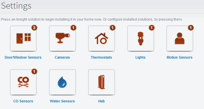
To add a thermostat, click on SETTINGS in the toolbar.
Click Thermostats to display the thermostat settings screen.
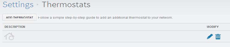
Click Add Thermostat and follow the onscreen prompts.
Resetting
The RESET button is located on the bottom surface of the OPTIMA and can only be accessed with a pin. When pressed, the RESET button will return the OPTIMA to default values as follows:

RESET WILL NOT CLEAR:
• Country and related settings (time zone and temperature units)
• Networking information
• HVAC system type
After reset, the OPTIMA will look for the hub or gateway from before the reset. The OPTIMA will only connect to another network when the PAIR function is performed.