Installaing
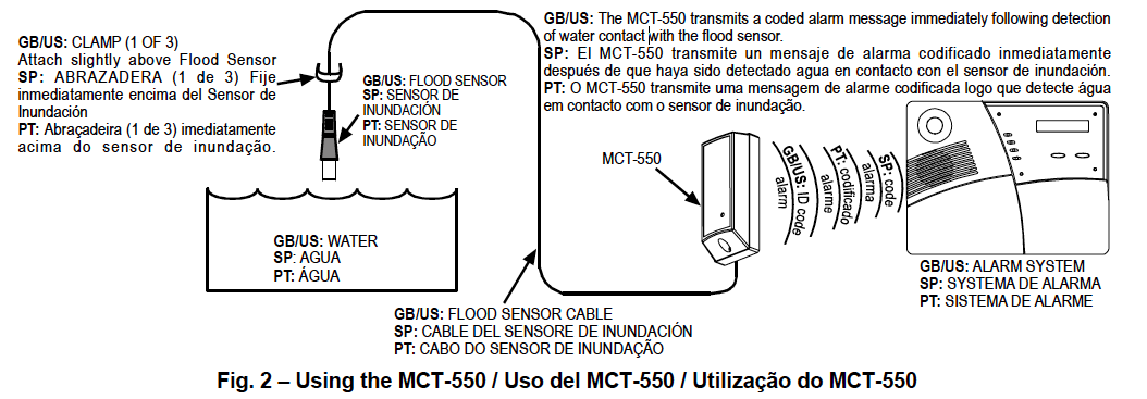
- Attach the flood sensor near the floor.
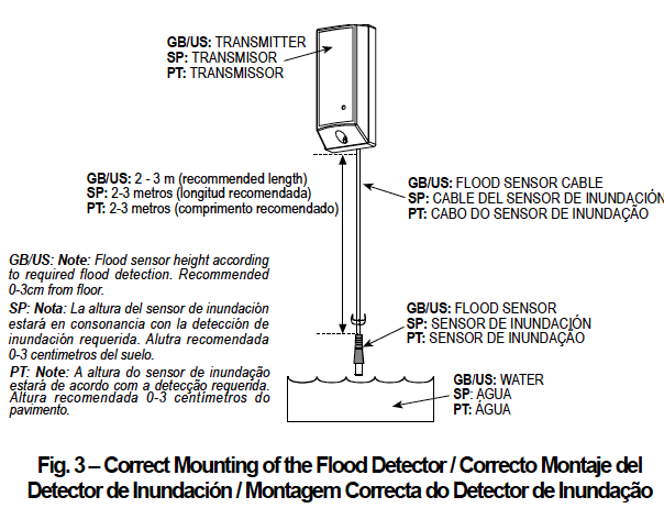
- Secure the flood sensor and its cable to the wall using the three wire clamps. One clamp should be fastened immediately above the flood sensor. The flood sensor should be installed only in a vertical position, and facing downward. The remaining two clamps can be used as required (Figures 2 and 3).
Note: To provide better protection against rats, it is recommended that the flood sensor cable be placed inside a metal/plastic pipe.
- Attach the transmitter to the wall. The transmitter should be placed as high up as possible on the wall to improve communication and to prevent the transmitter itself from coming into contact with water in the event of flooding.
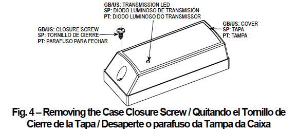
- Remove the case closure screw (Figure 4), then remove the unit’s cover (Figure 5).
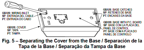
- Flex out the circuit board retainer (Figure 6) and detach the circuit board from the base.
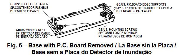
- Hold the base against the mounting surface and mark the 2 drilling points through the mounting holes.
- Drill the holes and fix the base to the wall using the 2 screws with countersunk heads supplied in the package.
CAUTION! Screws with other type or size of head may short circuit the bottom side of the printed circuit board.
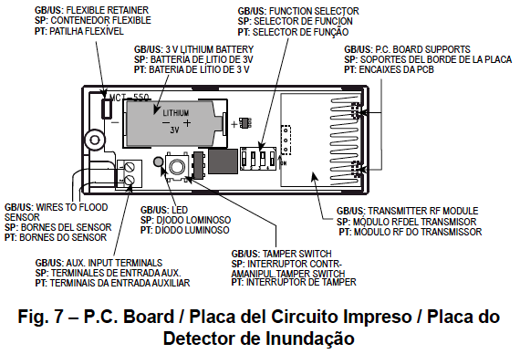
- Insert the edge of the P.C. board with the RF module into the edge supports, and press the other edge against the flexible retainer until it snaps home with a click.
- Clamp the two wires of the flood sensor cable into the auxiliary input terminals, as shown in Figure 7 (the wires can be inserted in any order).
Preparing For Use
Switch Functions
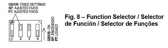
The MCT-550 has a 4-position DIP switch function selector (Figure 8).
Setting the Switches
Set the function switches as desired prior to applying power. Use a ball point pen or other pointed object to shift the switch levers. The ON position is indicated by the arrow on the switch body.
Testing
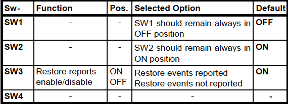
Before testing, set DIP switches SW3 and SW4 as required for the particular application.
- Insert the battery between the battery clips, at the correct polarity. For proper operation, only Lithium battery (Panasonic type CR-2 or equivalent) should be used. Press the tamper switch once and release it.
Note: Since the cover is removed and power is applied, a tamper situation exists. Verify that the MCT-550 transmits(the LED lights briefly) once every 3 minutes, regardless of SW4 setting.
- When you are satisfied that tamper alerts are transmitted properly, put the cover on to return the tamper switch to its normal (undisturbed) position. Wait slightly over 3 minutes to verify that tamper transmissions cease. If all went well, secure the front cover to the base with the case closure screw.
- Thoroughly clean the flood sensor with a rag. Bring the flood sensor into contact with water and verify that the transmitter LED lights, indicating that transmission is in progress. If SW4 is ON, wait 3 minutes to verify that the transmission is repeated at 3-minute intervals.
- Dry the flood sensor using either blotting paper or a rag, thus restoring it to the undisturbed state and observe the LED. If SW3 is set to ON, a “restore” transmission will now take place.